Wednesday, January 28, 2015

Common questions - ADC injected mode, slowed end, ..

There is some points I would like to clarify:

First little terminology attribute - recently I re-read a lot of docs about Cortex ADC features, and have noticed that right word for ADC under event-chaining called "injected mode",  a mode where the ADC conversion can be "injected" during the conversion of regular channels due to some trigger. Proper label added.

Why output on last project uses PWM mode instead of simple I/O? 
I leave it not because I'm too lazy to change pin chart, at least not only for this reason. Main reason is optional possibility for slowed end of moving.  It can be easy realized for simple DC motor by half-filled PWM output before "off" switch position. Or even by proportional law, depends on actual distance.

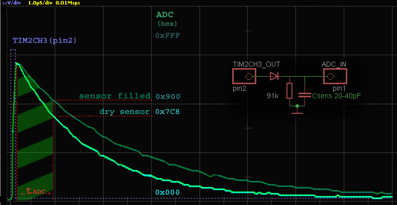
Why capacitive fluid level sensor uses some more complicated hardware, instead of famous cap-meter-with-arduino-uno?  
Jon's idea simple and elegant, but aimed to table measurements. In industry one of plates usually grounded for shielding from external RF noises (and/or to prevent leaking internal noises outside). But Jon's method can be suitable for Cortex chips also, with benefit of four times less input capacitance (7pF instead of 30pF in arduino uno ).  And I already got some ideas in this field.

Is it possible to use such "naked" inputs and outputs in real life sensor design?
I suppose it's a bad idea. These simple schematics provided for educational purposes only, in real life I can recommend at least additional zener diodes and buffered output, especially if you intend to use sensor in places more important than light shutters.


Monday, January 5, 2015

Inductive Proximity Sensor

Inductive proximity sensors are typically used to detect the presence or absence of a metal target and the output often emulates a switch. We can meet it in almost every area of factory automation, transport, home automation. Every place where necessary to know when moving part to stop. They use a high-frequency electromagnetic AC field that interacts with the target. We may say it's a kind of low-range metal detector.

flat printed coil
This example uses flat printed coil as a sensing inductor, that noticeably simplified hardware part. This coil easy can  be drawn in minute by scripts in Eagle. However, it can surely sense metal objects in distance 0.1" (2-3mm) or even aluminum foil, so we can track non-metal surface also, just stick a square inch of foil . No additional magnet-conductive core needed, for quick attempt works even hand-winded coil with ten turns of any wire on 1" diameter base.


Schematic twice more complicated. then previous sensor, but two diodes and two resistors with one capacitance not a big issue, isn't it? Like in previous one,  all started by master timer, however here impulse starts faded RF sin wave (~10MHz) on coil by L1C1 chain. If metal target close enough, sin wave fades more, because target act as short-circuited secondary coil. Next this RF impulse comes through second diode, and performs detection of envelope curve on ADC internal RC chain (8pF 50kΩ). Now we have to measure this DC "hill" just in time it comes, and event chaining help us again.

Code example almost the same, just a few differences. In main cycle -  proportion replaced by simple  on/off switch with hysteresis. And off cause, another constants, and another ADC timing.  Output (pin3) high(1) when coil closed by metal target, low(0) when open.

Event chart and other software details remains the same:
code compiled in Keil µVision 4 .71 with standard libraries for STM32F0.

UPD:
Recently discover new variant of schematic - v2 works better.
Charts almost the same, except direct leaking TIM pulse front through diodes.
However, this circumstance don't disturb us, because ADC turns on little later.


Thursday, January 1, 2015

Toner Transfer for PCB

Toner Transfer PCB tssop20 Cortex M0
tssop20 CortexM0 PCB
Recently I get sight to back of my laser printer, old good HP 4P, and realized that there is kind of anniversary - 20 years of work. Fist 10 years was spend in publishing, next decade I've used it in  PCB prototyping and custom production up to A4 format size.
Usually people think toner transfer tech is kind of DIY methods, painful way to save some money. However, for me money economy not so important, like to save a lot of time and avoid worry.
Toner transfer allow me to complete whole cycle of  PCB design in my workshop, and make all possible mistakes (and correct it) before sending PCB file to board manufacturing service. Usually I need about 1-2 day to make PCB in service,  and a whole day to bring PCB back. And what a pity when returned PCB had an error! In my workshop all this design loop takes 10 min instead of 2-3 days. Considerable saving of time, is't it? For transport spendings and nerves too.
As a base for transfer at large sizes I use glossy back  paper from sticker film (waste product in front panel design). But for small sizes (and high accuracy) thin aluminum foil is perfect.
Key is right temperature, I always use digital measuring with calibrated thermo-pair, ±5° error may kills everything. For my type of toner optimal 105C°, but most of modern printers use more high temperature toner. Better way to buy laminator machine, but I haven't find yet the one, that can swallow some of my 2.5mm thick PCBs, without deep modification.
Etching in ferric chloride (or another solution, it doesn't matter) needs to be quick, not more than 3-5 min. If it becomes longer, make solution more dense.

Sunday, December 21, 2014

Prototype Board for STM32 tssop20

PCB STM32F050F4P6 tssop20
PCB STM32F050 tssop20
Feel like I need to explain what type of PCB used in this and other similar projects. This simple 1-sided PCB designed in  Eagle, has dimensions 1"x1.2"(2.5x3cm), and intended to use in compact analog-digital devices. There are two connectors: one for A/D signals (up to 9 channels of  12-bit ADC or in/out for up to 32-bit timers) another for SWD prog and debugging, power source (+3.3v) and UART(or I2C, or additional PWM).

Recommended values
C10 = 0.1μF
R-R4 = 0-100 Ω
L up to 560 Ω
C11 up to 1μF
BOOT pad (under C11) short on left (grounded)
C1- C9 are optional, usually this pads used for prototyping or temporary components.
Z1 optional too, if used, don't forget change system_stm32f0xx.c setting to HSE.

PCB connected via SWD
Chip STM32050F4P6 comes with nice tssop20 package, not so hard to solder even by hand. In my practice solder this package much more easy than tqfp4x or large lqfp packages. On photo early PCB version connected via SWD with programmator on "discovery" board (and also powered from it ).


Wednesday, December 17, 2014

Fill level sensor prototype photos


Capacitive fill level sensor
sensor prototype
Now we can take a closer look at hardware part. It's very simple: two aluminum tubes with plastic spacer on one side. Outer tube grounded, inner wired through spacer by small hole, tight sealed with wire. Spacer must be fully hermetical, especially if  you intends to work with flammable or easy evaporated fluids like gasoline.
Why gasoline? Because it most complicated fluid for capacitive measurements. Gasoline has very low permittivity close to 2 (it means 40 times less than water). Low permittivity leads to low spread of capacitances. It means that filled sensor will have only twice more capacitance than dry one. Literally, we need to measure spread between 20 and 40pF. And sensor copes with it pretty well, shows only 2.5% nonlinearity. It means that kind of sensor can be used for most hard tasks like any types of fuel, refrigerants or even liquid gases.

Monday, December 15, 2014

Is there some RTOS?

Code example for capacitive level sensor seems short and simple (there is even haven't used interrupts!), but some parts may looks quite unusual.

First, seems like there is no RTOS. Yes, there no side RTOS, just hardware drivers. However, if look closer, we realize that main cycle plays the same role  like a main cycle in any RTOS, clocked by hardware timer.

event chart, hardware-driven RTOS

Difference in who clocks CPU - actually there TIM2 triggers ADC,  then ADC starts measurements, and only when it done, ADC triggers main cycle. All CPU needs to do is get fresh data, and work with it. We may say there is a very small hardware-driven RTOS. Or, as was mention before, there is not a emulation of hardware device by CPU, but chains of peripheral devices, configured and serviced by CPU.

This brings us to another difference - event chaining procedures. This procedures connect hardware in functional chains, it allow to work together without disturbing CPU. Actually, in this example peripherals drives CPU, and CPU just services peripherals. All other time CPU free to think or sleep. First may be used for filtering or statistic, second - to lowing current consumption.

Because of simplifying code example, there are simple pooling loop in ADC cycle, and it's means that current consumption close to maximum 14mA. But consumption can be significantly lowered close to zero by using sleep mode with interrupt routine. By the way - event chaining appear not to replace interrupts, but to complement it from hardware side, for unloading CPU from extrinsic tasks.

Code compiled in Keil µVision 4 .71 with standard libraries for STM32F0.

Final binary code not exceed 7kb in size, and leaves free 6kb even for cheapest chip in line like STM32F050F4P6.


Saturday, December 13, 2014

Too much impulses

Usually, low capacitance measured by sending high frequency (from hundred kHz to tens MHz) impulses through it, and look at attenuation. But for capacitance there is enough just one pulse. We can lowed quantity of impulses for million times,  spend much less energy, and reduce radio interference. So, let's dispense just one pulse. And it radically simplified hardware part:


Yes, just diode and resistor! Who can imagine something more simple? But simplicity in hardware needs kind of tricky (but not complicated) software. First, we send short pulse from timer output, charge sensor, and measure how voltage drops in discharge on resistor. This trick possible only with perfect synchronization between timer and ADC. And event chaining help us.

Timer pulse needs right width. If it will be too short, pulse can't charge sensor high enough, but if pulse too long, ADC will  measure top of pulse itself, instead of voltage falls curve on capacitance. Ideally, pulse width need to correspond with ADC "switch on" delay, it about 0.2μs.

In that case all we need is read ADC data reg, because all other work will be performed inside Cortex ADC (a couple of sampling shots and approximation). Actually, we measure not a point, but  slope area between start and stop of ADC sampling time (green stripes on pic). And this slope pretty close to linear dependence of  capacitance.

Friday, December 12, 2014

Just measure this, thats all.

Easy to say, but there are question of measuring real low capacitances. For instance, for tubes:

length (l)=120millimeter =0.12meter
outer conductor diameter (b)=28millimeter =0.028meter
inner conductor diameter (a)=19millimeter =0.019meter

This wonderful cylindrical capacitor calculator shows only 17pF for dry one!

Conversions: 
permittivity (ε)=8.85picofarad/meter =8.85E-12farad/meter (air)
capacitance (C)=17.20 picofarad

But inside every Cortex chip ( for instance: STM32F050F4P6) there are a powerful ADC, with near 1μs sample time, 7pF input capacitance, and 12bit resolution. And it can be synchronized with other peripheral (e.g. timers) by dedicated hardware link, configured with other peripheral registers. This feature called event chaining.

Let's calculate time constant for dry sensor with 91kΩ resistor (assume this enough for low interference) RC Time Constant Calculator says 1.547μs for 17pF 91kΩ. Seems like ADC can catch it! Notice, we need to sample fist half of curve, because this part less nonlinear.

All this give us a hope, that for this task we don't need any additional active components like FET or op-amp. Just  resistor and diode!


Thursday, December 11, 2014

Capacitive fluid level sensor

First device in practical examples - sensor for measuring level of a liquid.

Every liquid need to be measured: from liquids in medical life-saving devices and fuel in plane you fly, to refrigerant fluid in industry scaled fridges at food plant and oil in tanks.

Best way to detect  fill level of non-conductive (and conductive also) liquids is using it as dielectric in kind of electrical capacitor, combined of two plates, (in most cases, cylindrical) with gas gap between.

More about: what-is-level-sensor on engineersgarage.com


Effective dielectric constant describes permittivity of liquid
" permittivity relates to a material's ability to transmit (or "permit") an electric field "
Most gases had low dielectric permittivity, instead of liquids, and quantity of liquid in gas gap noticeably rises capacitance. Just measure this, thats all.

Industry very interested in this type of sensors. It not only suitable for liquids itself: this way accurate also on liquid foam, and even in cases were needs to know quantity of liquid in substances (e.g. water in soil).

One or both of plates can be isolated, to avoid resistive loses or to protect plates from chemicals. Or both of them can be leaved non-isolated, if sensor uses in additional resistive measuring. For instance: detecting water in gasoline or salt in water.

Link to some other similar projects :
Capacitive Liquid Level Sensor on mudventions.com
Liquid Level Sensing is Key Technology for Today’s Systems on digikey.com

Wednesday, December 10, 2014

Event-chaining in peripheral

Here will be placed examples of some devices uses Cortex M0 microcontroller. This low-consumptive 32-bit core MC's fast enough, had impressive peripheral, and easily programmed by high level language (C++). Here also enough space for data logging and statistic.

But main benefit is new type of connection for peripheral, that allows event-chaining between inner peripheral devices as timers, ADCs, memory. It gives simple and sure synchronization between devices by excluding software delays. Reduces using central processor (CPU) , it lowing current consumption and keeps CPU free for math and control. This is simple and quick way to create real-time low-consumptive devices with high reliability. Moreover, seems like there is a great milestone from emulation electronic device by CPU, like it was before,  to fully CPU-independent (except clocking) real-time electronic device inside chip, just configured and serviced by CPU.