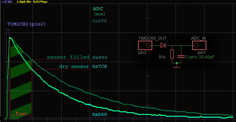
Usually, low capacitance measured by sending high frequency (from hundred kHz to tens MHz) impulses through it, and look at attenuation. But for capacitance there is enough just one pulse. We can lowed quantity of impulses for million times, spend much less energy, and reduce radio interference. So, let's dispense just one pulse. And it radically simplified hardware part:
Yes, just diode and resistor! Who can imagine something more simple? But simplicity in hardware needs kind of tricky (but not complicated) software. First, we send short pulse from timer output, charge sensor, and measure how voltage drops in discharge on resistor. This trick possible only with perfect synchronization between timer and ADC. And event chaining help us.
Timer pulse needs right width. If it will be too short, pulse can't charge sensor high enough, but if pulse too long, ADC will measure top of pulse itself, instead of voltage falls curve on capacitance. Ideally, pulse width need to correspond with ADC "switch on" delay, it about 0.2μs.
In that case all we need is read ADC data reg, because all other work will be performed inside Cortex ADC (a couple of sampling shots and approximation). Actually, we measure not a point, but slope area between start and stop of ADC sampling time (green stripes on pic). And this slope pretty close to linear dependence of capacitance.

No comments:
Post a Comment